Wire Bonding insights at your fingertips
Here we regularly present news related to wire bonding. These may be our own activities, brief food for thought or summaries of interesting publications. So it's worth spending a little more time here.


BAMFIT – From an Evaluation System to a Remanufacturing Platform for Heavy Wires in Power Electronics
BAMFIT (Bondtec Accelerated Mechanical Fatigue Interconnection Test) enables a rapid assessment of the reliability of thick-wire bonds for production monitoring and process development. The method uses ultrasound and a special gripping unit to apply mechanical loads directly on wires. The further development of the system provides insights into bonding processes and material properties and supports there conditioning of battery modules, control units and power electronics.
Customer demands are rising, validation efforts are exploding.
New wire materials, higher operating temperatures, changing chip designs, tighter tolerances. The demands on your bond connections are growing.
Customers today expect more detailedevidence of connection quality than just a few years ago. At the same time,corrosion-resistant alloys ...
Successful Project: A Customer's Voice on Multi-Client Project’s Impact
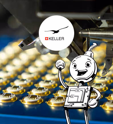
Our project partner, KELLER Pressure, has just published an article highlighting the value of our collaboration through the Bond-IQ multi-client projects. In their article “Quality Starts on a Small Scale,” KELLER explains how Bond-IQ's research initiatives—such as QUALSi (focused on aluminum bonding wires) and surf:guide (defining bond surface standards)—are enhancing their understanding of critical quality factors.
We’re proud to see our work making a difference. Their recognition reinforces the strength of our partnership and our shared pursuit of engineering excellence.
The Pull Test: Simple in Theory, Complex in Practice
The pull test seems straightforward - use a hook to pull the wire bridge upward and measure the breaking force. It's been standard since MIL-STD-883 across automotive, military, space and ...

The Pull Test: Simple in Theory, Complex in Practice
Need to test your wire bond strength?
The pull test seems straightforward - use a hook to pull the wire bridge upward and measure the breaking force. It's been standard since MIL-STD-883 across automotive, military, space and consumer applications.
But here's what most people overlook:
📍 Hook Position Matters Try this experiment: Create 50 bonds, then test 5 at the first bond site, 5 at the second site and 5 in the middle. You'll see different values despite the bonds being identical. Why? The closer your hook is to a bond site, the more stressed that site becomes, which changes failure patterns and force readings. Use your remaining 35 bonds to verify this consistent, predictable relationship.
📐 Angles Change Everything As you pull, different angular triangles form at each bond contact. This affects the distribution of vectorial force, which changes your measured values even though the bond strength hasn't changed. It's pure mathematics, not bond quality. The angles determine how the force vectors distribute from the hook position.
🪝 Hook Selection is Critical Use 2-3 times the wire diameter. I prefer 3 times. What if it's too thin? The hook will cut the wire instead of testing the bond. You're measuring cutting force, not bond strength. There's double deception: the wrong failure mode and the wrong force value. Modern testers with fine sensors can handle precise measurements, but only if your setup is correct.
📊 Standard Tables Aren't Enough Evaluating a test result requires more than just looking at tables or diagrams. First, you must correct for mathematical influences, material factors and human errors.
🎯 Even "Non-Destructive" Tests Matter Do you think your non-destructive tests at low force are safe and harmless? Without an understanding of the mathematics of force distribution, it is impossible to know how much force actually reaches the bond site.
Resources & Key Takeaway
1️⃣A publication in which the formulas were analyzed in great detail and the errors of existing formulas were also uncovered. https://www.bond-iq.de/blog-publications/publication-011
2️⃣ A small online tool that helps understand how the relationships between angles and forces work. https://www.geogebra.org/m/smzbzxxb
3️⃣Engage with DVS bulletin 2811, which has always taken material properties into account when testing wire bonds. https://www.bond-iq.com/dvs2811
Wire Bonding Surfaces in Power Electronics
Despite ongoing miniaturization and performance improvements in power electronics, wire bonding is still essential today. Wire bondable surfaces must provide an optimal combination of electrical conductivity, mechanical stability, and resistance to aging and corrosion processes. This article introduces the most important industrially established metallizations for wire bonding, highlights typical sources of error and their effects on bond quality, and summarizes cleaning processes.
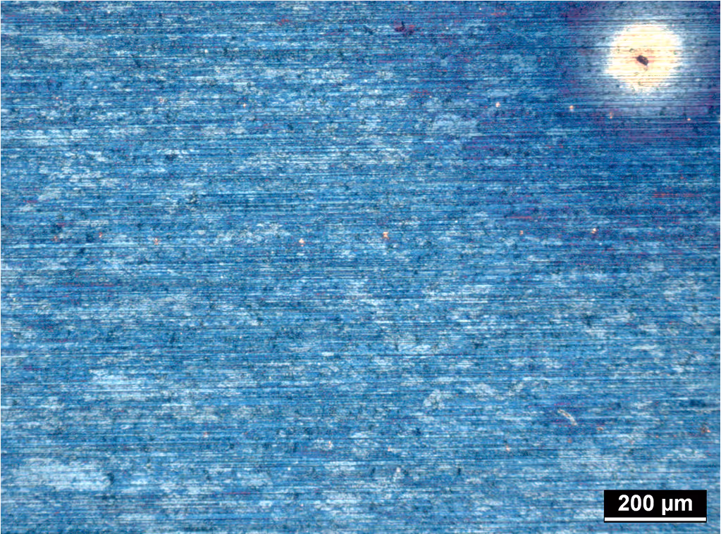

What it is?
The correct answer is copper oxide.
However, this is not an oxide that forms spontaneously under normal environmental conditions, but rather a deliberately aged sample. The material was thermally aged for several minutes at a temperature of 200°C 🔥.
The sample is a smooth-rolled, high-purity copper sheet (OF copper) with a purity of 99.9%. The surface of the sheet material was very smooth due to the rolling process and was additionally protected from environmental influences by a plastic film. This protective film was removed before the tempering process. The subsequent thermal stress at 200°C led to the formation of a visible oxide layer on the surface.
In this state, the surface is no longer suitable for wire bonding. Although it might be possible to make contact with a thick wire, resulting in initial adhesion, this contact can be easily broken again using simple tools such as tweezers or a pull tester 💪🏻. This indicates a poor mechanical and electrical connection.
Heavily oxidized copper surfaces are generally unsuitable for wire bonding because the oxide layer prevents the formation of a metallic bond. To restore bondability, the oxide must be removed. This can be done, for example, by means of a reducing plasma or a targeted wet chemical surface treatment – preferably under conditions that selectively attack the copper oxide without damaging the base material.
Thermosonic Bonding: Analyzing the Effects of Ultrasound, Heat, and Metallurgical Processes on Gold and Copper Wire Bonds
In the field of microelectronics, wire bonding represents a pivotal process, utilized for the interconnection of minute wires between a chip and a substrate. The research project is concerned with the comprehension and enhancement of the ball bonding process, which entails the utilization of gold or copper wires.
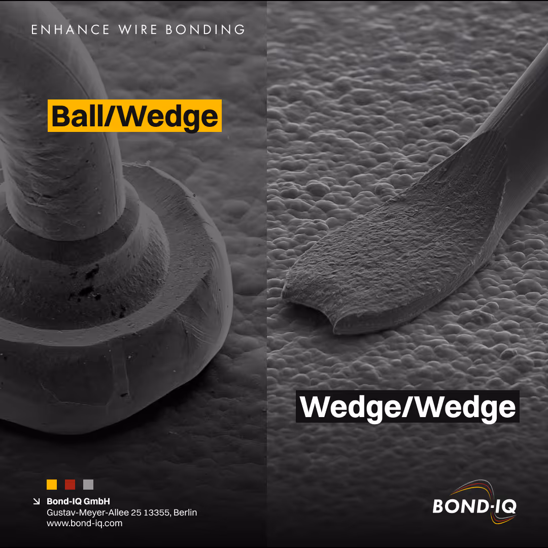
Ball/Wedge or Wedge/Wedge wire bonding? An ongoing debate 💬
One post certainly cannot fully resolve this complex issue. Even a short webinar dedicated to the topic would only scratch the surface. The optimal bonding method for a specific application depends on ...
Ball/Wedge or Wedge/Wedge wire bonding? An ongoing debate 💬
So here are some of my thoughts 💭.
One post certainly cannot fully resolve this complex issue. Even a short webinar dedicated to the topic would only scratch the surface. The optimal bonding method for a specific application depends on various factors:
🔸 Material costs
🔹 Height differences that must be overcome
🔸 Requirements for reliability and qualifications
🔹 Targeted production volumes and cycle times
🔸 Limitations regarding environmental temperatures
🔹 Layout and design, particularly of the semiconductor
🔸 Environmental conditions of the intended application
🔹 Availability of expertise, internally and with suppliers
🔸 Electrical parameters that must be considered
🔹 Availability and specifications of metallization
🔸 Specifications regarding the materials used
🔹 Working areas that need to be covered
Certainly, I may have overlooked one or two points in this list.
Selecting a wire bonding method is a multi-step process involving multiple decision-makers and experts. Since no one person has complete responsibility for all the influencing factors mentioned above, this decision cannot be made by a single individual. Therefore, it is crucial that the decision-making committee includes all necessary competencies.
I have encountered numerous projects in which the choice of bonding method was prematurely restricted because one method was mentioned too often or too early on. This resulted in the method becoming favored among suppliers and decision-makers without sufficient analysis.
Will the process always yield one optimal solution? Often, yes. Often, one method stands out by meeting most of the requirements. However, sometimes both methods are only a compromise, forcing us to choose the lesser of two evils. Alternatively, a complete re-design tailored specifically to one bonding method might be considered. With this approach, the method is chosen first and then the design is adapted accordingly. Whether this is the best approach cannot be generalized. However, it remains one of several possible strategies.
Are there customers who haven't chosen the optimal solution? Yes, such cases exist and will continue to occur.
Therefore, our support will remain essential in the future. Our mission 🚀 is to assist companies in implementing stable wire bonding processes – and selecting the appropriate wire bonding method is crucial for achieving a stable wire bonding process.
Evolution of Semiconductor Bonding Wires: From Gold to Copper and Silver Over 25 Years
This study examines the evolution of bonding wires utilized in semiconductor electronics over the past 25 years, with a particular emphasis on gold (Au), copper (Cu), and the emerging utilization of silver (Ag) wires. Bonding wires are of paramount importance for the interconnection of semiconductor chips with other components in electronic devices, such as mobile phones and computers.
How Ultrasonic Power and Intermetallic Formation Work in Thermosonic Ball Bonding
This research project is concerned with the subject of thermosonic ball bonding, a process which is employed in the field of microelectronics for the purpose of connecting components of a relatively small scale. The objective of the study is to enhance comprehension of the manner in which materials behave during this process. Thermosonic bonding is a process that employs the combination of heat, ultrasonic vibrations, and pressure to create connections between a wire, typically gold or copper, and a substrate, such as aluminum.
The study examines the formation of bonds and the microscopic alterations in the materials utilized.
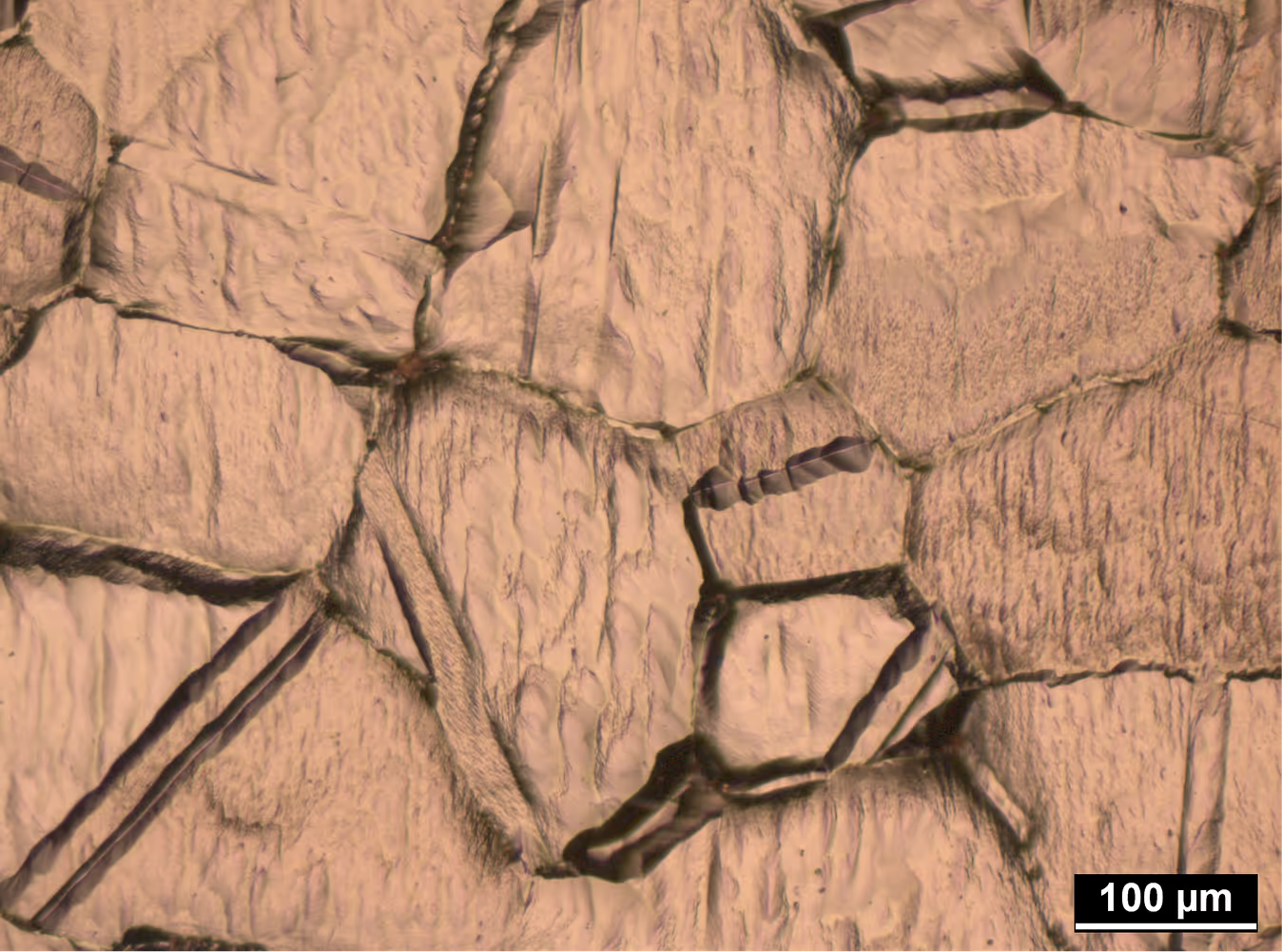
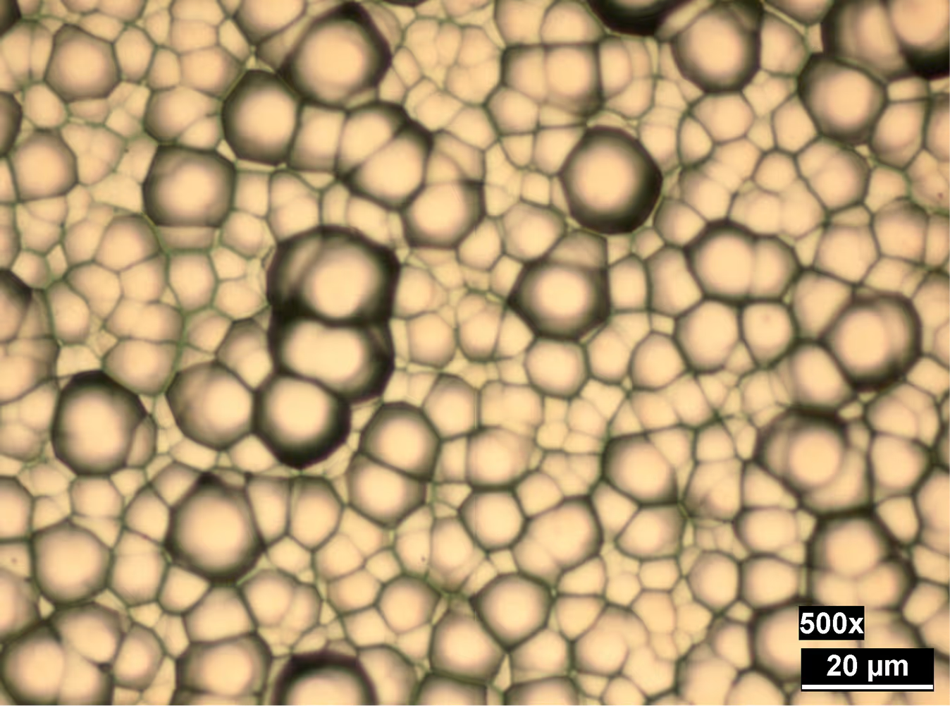
What it is?
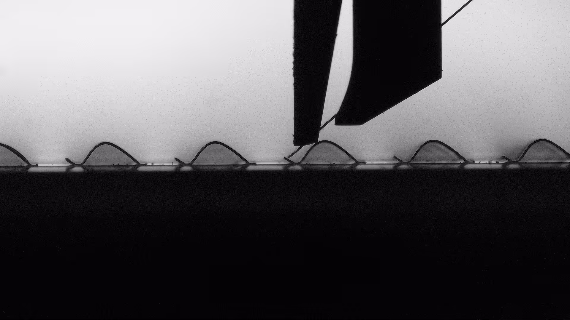
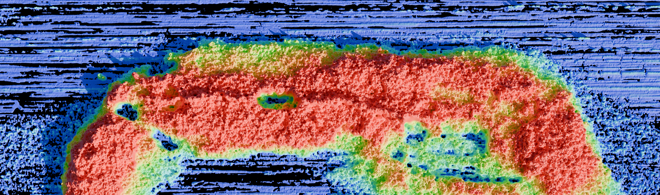
The image shows the surface of a DCB substrate (Direct Bonded Copper, also known as DBC), a material widely used in power electronics due to its excellent thermal and thermomechanical properties. The structure typically consists of an Aluminum-Oxide based ceramic onto which copper is applied on both sides without intermediate layers using a diffusion based metallurgical process.
The copper is deposited without the use of additional bonding agents. During the high-temperature process (🔥 > 1065 °C), diffusion and recrystallization result in a highly pronounced grain structure with significant height differences – typically in the range of 10 µm to 30 µm.
Despite its coarse-grained structure, this surface is suitable for thick wire bonding. In particular, wire diameters in the range of 300 to 500 µm show very good results in wire bonding on DCB surfaces. However, the pronounced topography can cause problems with thinner wires (< 200 µm), especially during the wire cutting process. Therefore, surface pretreatments are often used to process fine wires. These treatments reduce the height profile without completely removing the basic grain structure.
The exact characteristics of the grain structure depend largely on the copper alloy and process parameters used. The influence of this microstructure on bond quality is currently the subject of industrial research, particularly with regard to processability in wire bonding.
As an alternative to DCB, AMB (Active Metal Brazing) is also used, which, thanks to the modified manufacturing process, also enables ceramic types such as AlN and SiN.
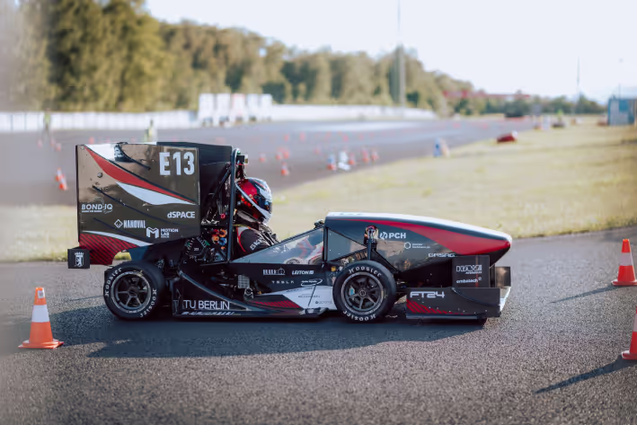
Racing Update 2024 - We are ready for the next step
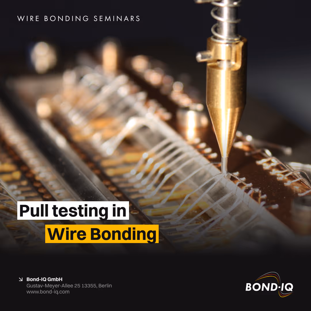
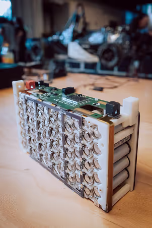
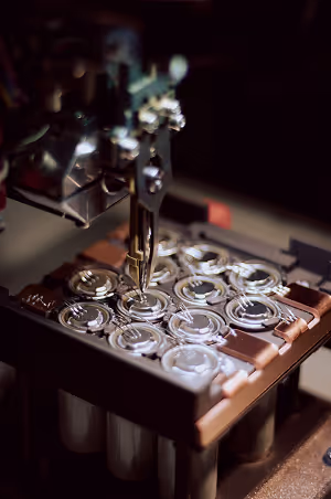
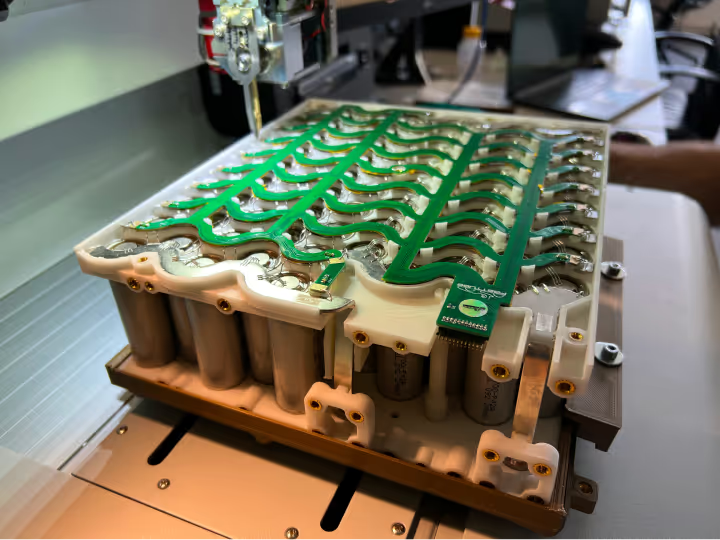
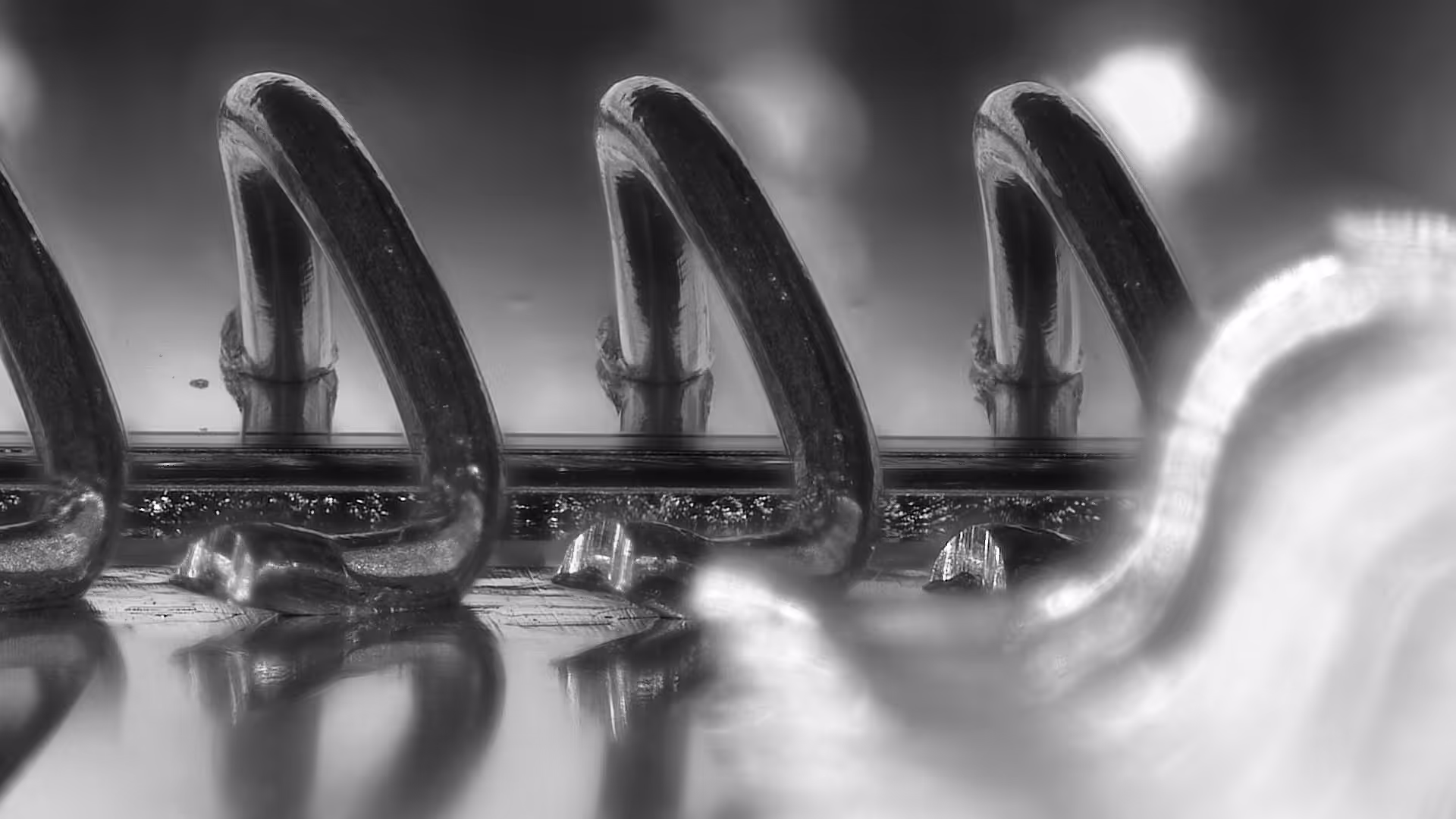
We have designed the battery packs completely without bus bars. Direct connection of the battery cells, cooling through the back of the cells – i.e. wire bonding on the cathode and anode on one side of the battery cell – and 3 wires with a diameter of 500 µm per battery shoulder for maximum performance. Wire lengths of up to 20 mm that will not sag and cause short circuits despite the vibrations of driving. This allows us to achieve the highest possible level of miniaturization for this type of cell and significantly reduce weight for an even faster racing car.
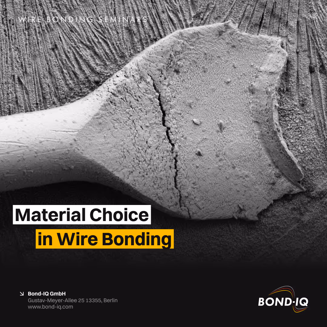
Material Choice in Wire Bonding
In wire bonding, materials aren't just inputs – they’re critical enablers of process stability and long-term reliability. Especially in ...
Material Choice in Wire Bonding
Wire Bonding: Material Choices That Make or Break Reliability 🔥
In wire bonding, materials aren't just inputs – they’re critical enablers of process stability and long-term reliability. Especially in high-reliability and high-temperature applications, choosing the right material system is fundamental.
Here’s a look at key insights and what the industry still needs to tackle:
✅ What We Know
Monometallic systems like Au-Au (e.g. Gold wire on Gold pad), Al-Al or Cu-Cu remain the Gold ⭐️ standard for high-reliability and high-temperature environments.
Processability ≠ Reliability: Just because a material combination bonds well doesn’t mean it will perform reliably under stress or over time. Just look at the combination of Aluminum and Silver – a timebomb in humid environment if not protected well enough.
Material purity matters: Even trace impurities – at ppm or low percent levels – can significantly affect both process behavior (e.g. loop stability) and in-field performance (e.g. corrosion resistance and intermetallic growth).
Aluminum deserves more credit: Despite being underestimated at times, aluminum often offers robust performance when correctly understood and applied. In particular, combining it with a 45-degree bonded head opens up so many degrees of freedom and improves process robustness. Looping may be limited in some applications, but even here, many challenges can be overcome with the right process knowledge.
🧩 What Is Needed
Agile material suppliers that can support fast-paced development cycles with rapid adaptation and technical support.
Smarter mechanical testing methods: Using force-displacement data more effectively, automating fracture pattern recognition and generating more insight from pull/shear tests. Even more advanced tests like BAMFIT that allow the in-depth inspection of interface formation
➡️ Publication Bamfit a rapid test for reliability of heavy wire bonds
➡️ Publication BAMFIT vs Shear test
➡️ Publication Advanced bonding interface inspection technique for process optimization in heavy wire bonding
Faster reliability assessments: Predictive modeling and accelerated testing strategies for fatigue and long-term performance are essential to meet today's time-to-market pressures.
⚙️ As the complexity of applications grows, so must our material understanding and testing methodologies. Let’s challenge assumptions, dig into the data, and engineer wire bonds that last.
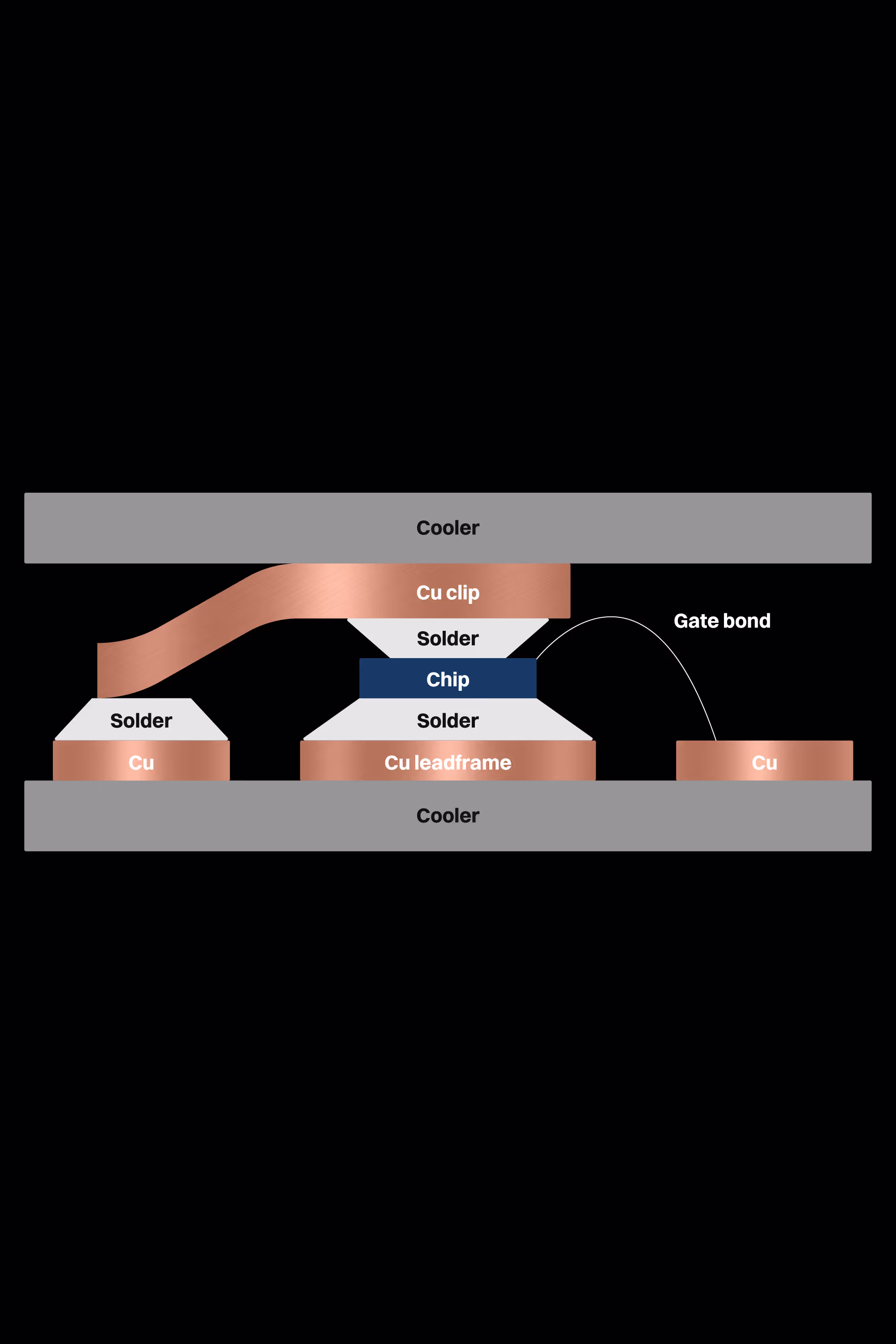
Can Copper Clips Solve the Reliability Problem in Power Electronics? A Look into Metallization Failures and Degradation
The publication's primary focus is on the reliability and failure mechanisms of the aluminum metallization layer utilized in power electronics. Power electronics, including the MOSFET (a type of transistor), are integral components in a multitude of devices, such as automobiles. Power cycling tests are typically conducted to observe the behavior of materials under conditions of elevated temperature and mechanical stress. Over time, these tests simulate the effects of real-world conditions on the chip, including temperature changes, which can cause wear and tear on the aluminum layer. This study examines the impact of switching from traditional aluminum wire bonds to copper clips on the performance and reliability of the module.
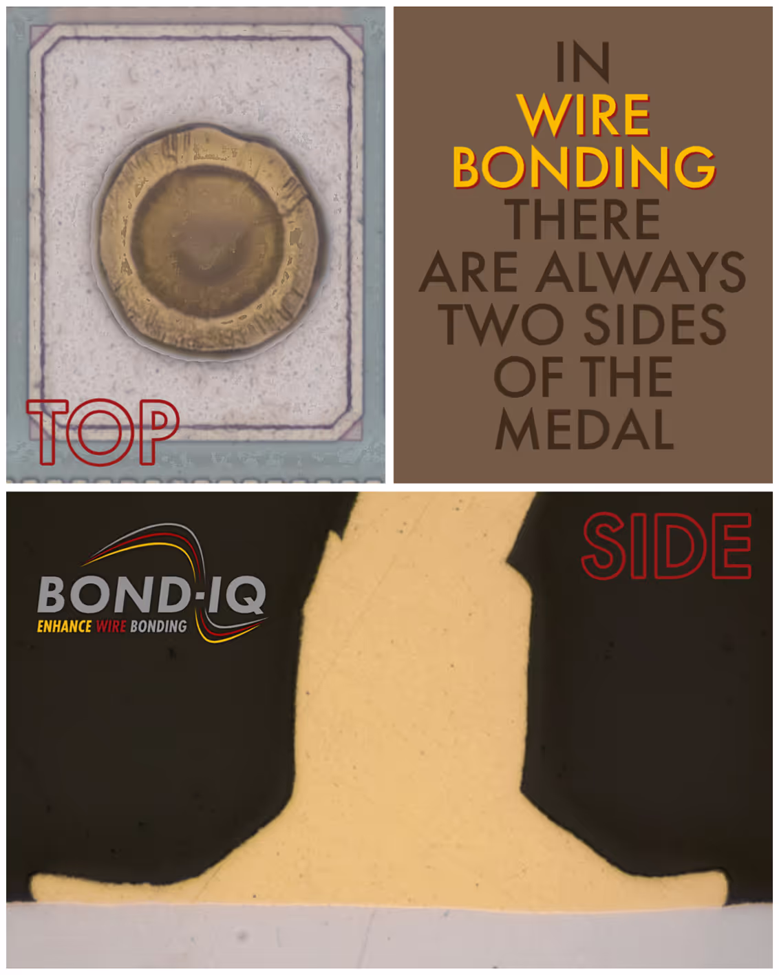
What it is?
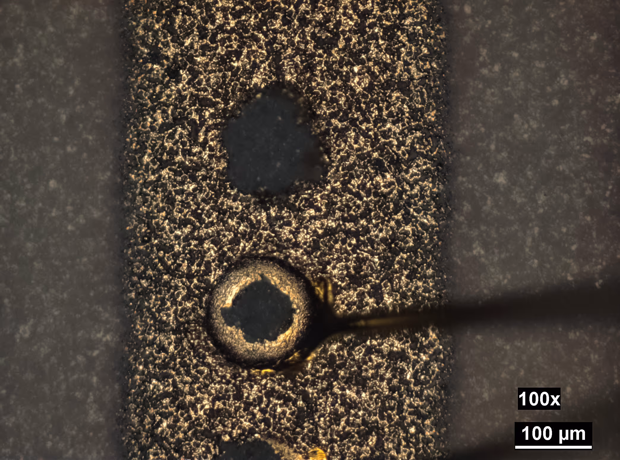
This is an ENIG surface. A typical ENIG surface features a rounded structure, which is formed by the underlying nickel layer. The ENIG layer is initially based on a copper layer – the conductor trace – which has a defined roughness, determined by the copper processing steps.
Nickel is then deposited on top of this structured copper surface. It grows in a "mushroom"-like fashion, radiating from nucleation points in all directions. When multiple of these "mushroom"-like structures converge, they create the characteristic rounded, nodular surface texture.
The specific shape and roughness of this structure – its peaks and valleys – are influenced both by the initial copper roughness and by the thickness of the nickel layer and the exact deposition conditions. As a result, ENIG surfaces often vary in their structure, making it essential to regularly monitor and measure the surface roughness. At the very least, inspection under a light microscope at high magnification is recommended.
Bonding tests on such surfaces reveal that elevated areas tend to be contacted preferentially. Deeply recessed, fully metallized regions may not be contacted effectively during the bonding process, as the wire cannot deform deeply enough into these structures.
That said, the rounded nature of an ENIG surface is generally highly favorable for wire bonding. This is clearly observable when comparing bonding results on sharp-edged, uncoated structures – which tend to perform poorly – with those on metallized structures featuring a rounded ENIG finish, which yield significantly better results.
ENIG stands for Electroless Nickel Immersion Gold and has additional characteristics worth noting, especially regarding the adhesion and quality of the gold layer on nickel, as well as the interface between these two metals. However, those topics will be covered in a separate post.
✅ Here the case is clear 🧐🕵️✅
It is simply not possible to achieve a stable wire bonding process if the surface quality is constantly changing. It is the supplier's task to ensure a homogeneous and good quality. And it is up to the customer who wire bonds to specify this quality. The supplier has to know which characteristics are important and how they have to be inspected. A visual inspection is the minimum here and should at least check the following details:
• Local discolorations and stains
• Drying stains
• Flux residues
• Solder spots#
• Filmic contaminations, e.g. oils, fats, fingerprints
• Local holes, scratches, scores
• Scoring marks resulting from mechanical processing, e.g. brushing, polishing, grinding
• Test needle imprints
• Exposed copper or nickel
There are always two sides to a coin 🥉. Those who do not care and specify well, but leave everything to their supplier, are part of the problem. So if you don't care, you then don't have to be surprised when things often go wrong. If it is as clear as in the picture of this post, the case is clear and the delivered lot goes back to the supplier - but that also costs resources and time, valuable time.
Wire Bonding Research? How to Spot the Good, the Bad, and the Misleading
If you’re reading technical publications about wire bonding, here are some insights I’ve gained over time that may help you determine their...
Wire Bonding Research? How to Spot the Good, the Bad, and the Misleading
🔬 Reading Scientific Papers on Wire Bonding? Here’s how to separate the wheat from the chaff.
If you’re reading technical publications about wire bonding, here are some insights I’ve gained over time that may help you determine their true value.
🪝 Pull test results on ball bonds
Often cited, but nearly useless when it comes to judging the bond interface quality. Don’t get misled by high pull forces alone.
🧵 Know your wire
Companies like Heraeus have changed naming schemes for wires over the years. In 2021 they changed the naming of thick wire types. As a result, older publications contain terms that are no longer in common use. Always check what generation or version is being discussed - small changes in alloy can mean big changes in behavior.
⚠️ More than the top layer matters
The entire metallization stack (not just the top layer) affects bondability and reliability. Good papers will mention this and contain details about layer thickness and composition.
🔬 Microscope images are gold
SEMs, cross-sections, bond footprints – a picture says more than 1000 test results when it comes to understanding real bonding conditions. Publications without proper images are missing essential information.
💥 Failure modes + numbers
Always look for shear and pull test results with failure modes. Numbers alone can’t tell you the story. Where the bond failed is more important than how hard it was to break.
📄 Sources are good – but…
References and links improve trust, but not necessarily quality. Always ask: Did this citation add value - or was it just filler?
🧠 Complexity needs space
If a technical topic is covered in only half a page, skepticism is warranted. Well-founded explanations of material behavior, bonding mechanisms, or process parameters require more space. Good papers take the time to explain these concepts thoroughly, while poorly written papers skim over them.
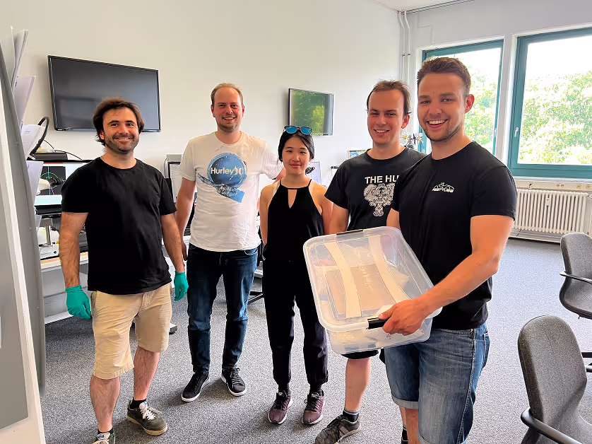
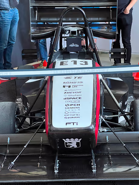
Bonding battery cells in the FASTTUBE TEAM racing car 2022
Since 2005, around 80 students from the FaSTTUBe team at the TU Berlin have been building a new racing car every year to take part in international and European Formula Student design and racing competitions. Since 2018 with an electric car and since 2020 driverless. Bond-IQ joined as a platinum sponsor in 2022, using thick wire bonding to wire the battery modules (including the driver architecture), which the development team converted from bags to 18650 cells in an impressive 3 months. As this technology is new territory for the FaSTTUBe team, we are always on hand to provide support. Whether it's a quick visit to check on a detail or a lightning-fast turnaround for a prototype. The FaSTTUBE team is fighting all the uncertainties and delivery difficulties of 2022. We will always be close at hand and will support you with all our strength and resources.
Racing Update 2023 - We improve the battery for an even better racing car
We have designed the battery packs completely without bus bars. Direct connection of the battery cells, cooling through the back of the cells – i.e. wire bonding on the cathode and anode on one side of the battery cell – and 3 wires with a diameter of 500 µm per battery shoulder for maximum performance. Wire lengths of up to 20 mm that will not sag and cause short circuits despite the vibrations of driving. This allows us to achieve the highest possible level of miniaturization for this type of cell and significantly reduce weight for an even faster racing car.
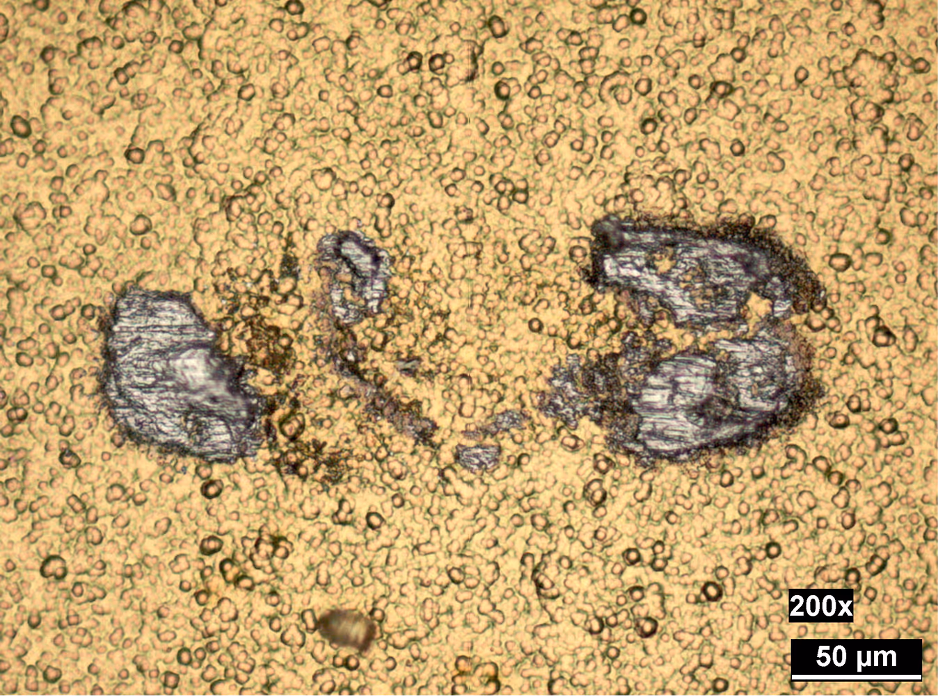
What it is?
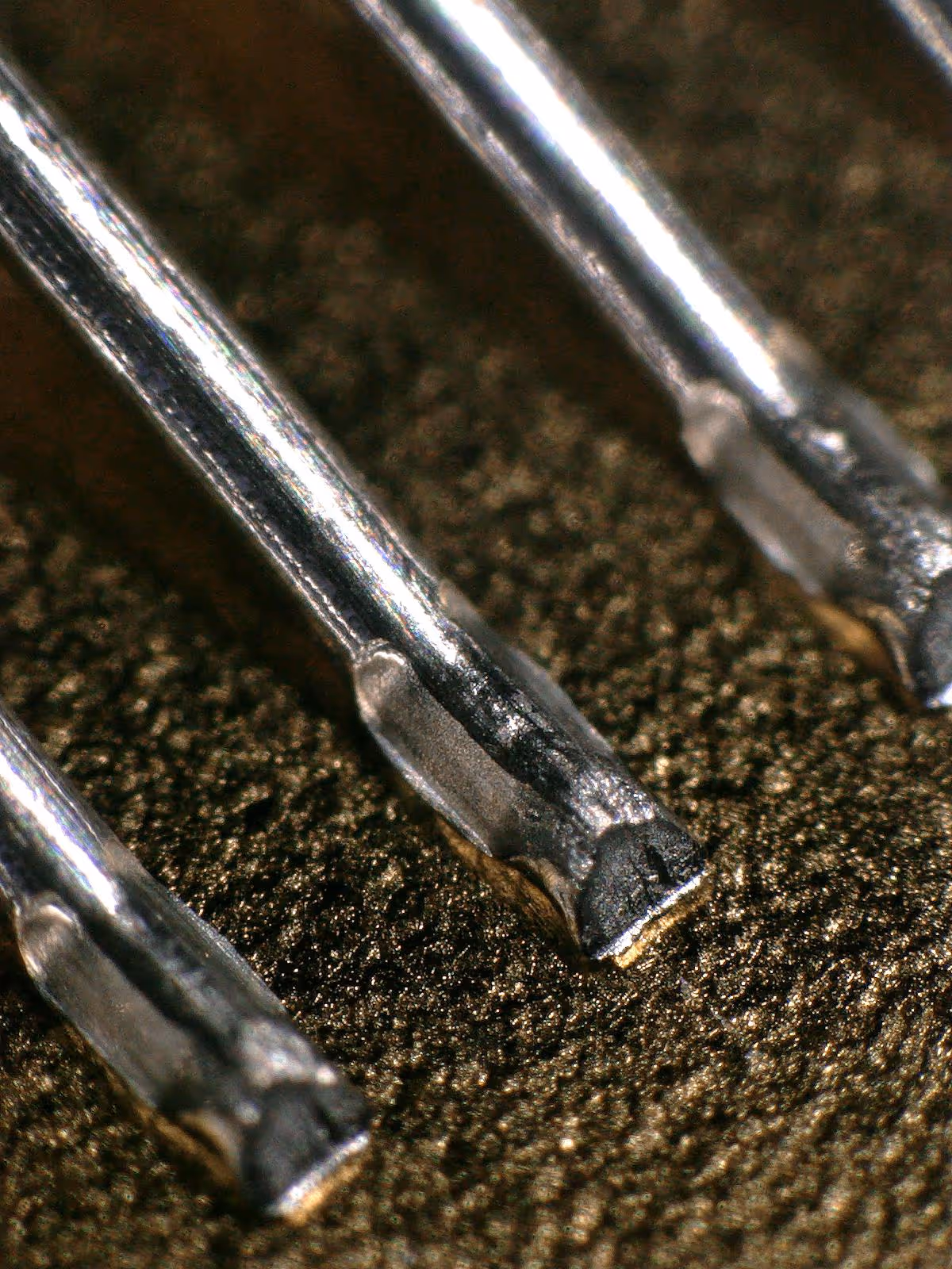
This is a region where an aluminum fine wire bond was detached during a pull test. This phenomenon is commonly referred to as a "lift-off". The actual bonding region – where gold and aluminum have formed an intermetallic connection – is only present on the left and right edges of the contact area. In the center, there is very little bonded surface. Instead, a large area of exposed gold is visible. No connection occurred between the gold and the aluminum in the central region.
The exact reason for this is difficult to determine from the image alone. On the left-hand side, slightly darkened areas are visible, which may point to a contamination. It is possible that a particle was involved, which then disappeared during the detachment – a loosely resting contaminant that was randomly involved.
Analyzing such lift-offs at high magnification 🔬 is always necessary. In the attached image, one can clearly see residual aluminum on the surface 🥳. However, there are also cases in which the surface layer itself peels off during the pull test. At low magnification, this may appear very similar to a standard lift-off and can be hard to distinguish. Only at high magnification does it become apparent that no bond could have formed in the first place because the surface detached during either the bonding or pull process.
Such image analyses are especially relevant for those involved in inspecting bonded contacts after pull tests. It’s also important to note that a lift-off can occur even during the bonding process itself – for example, while forming the wire loop. A small tensile force can already be enough to cause the bond to fail. In other words, the wires may not hold even during the bonding cycle within the bonder.
In all such cases, it is essential to identify the nature of the lift-off: whether it’s a classical failure due to poor adhesion or whether a delamination of the surface layer is the root cause.
A New Approach to Wire Bond Testing Could Improve High-Power Electronics Reliability
The objective of this study is to enhance the reliability assessment of wire bonds in power electronics, with a particular emphasis on the Highly Accelerated Lifetime Testing (HALT) methodology. In the context of electronic devices, wire bonding refers to a technique whereby thin wires are used to connect semiconductor components. With the passage of time, these bonds may succumb to failure as a consequence of wear and tear, particularly in the context of extreme temperature fluctuations. The researchers developed a mechanical testing method to simulate the failure that would naturally occur in wire bonds over time, thereby enabling them to predict the longevity of the bonds in real-world conditions.
New Standards in Wire Bonding: A Detailed Analysis of DVS-2811 for Automotive and Power Electronics
The authors examine the advancements in wire bonding standards for the European automotive and power electronics industries. Wire bonding is a method of creating electrical connections between semiconductor devices and their packaging using thin wires, which are of critical importance for the production of microelectronics, such as batteries. The study concentrates on the DVS-2811 standard, which provides guidance on the testing and inspection of wire bonds.
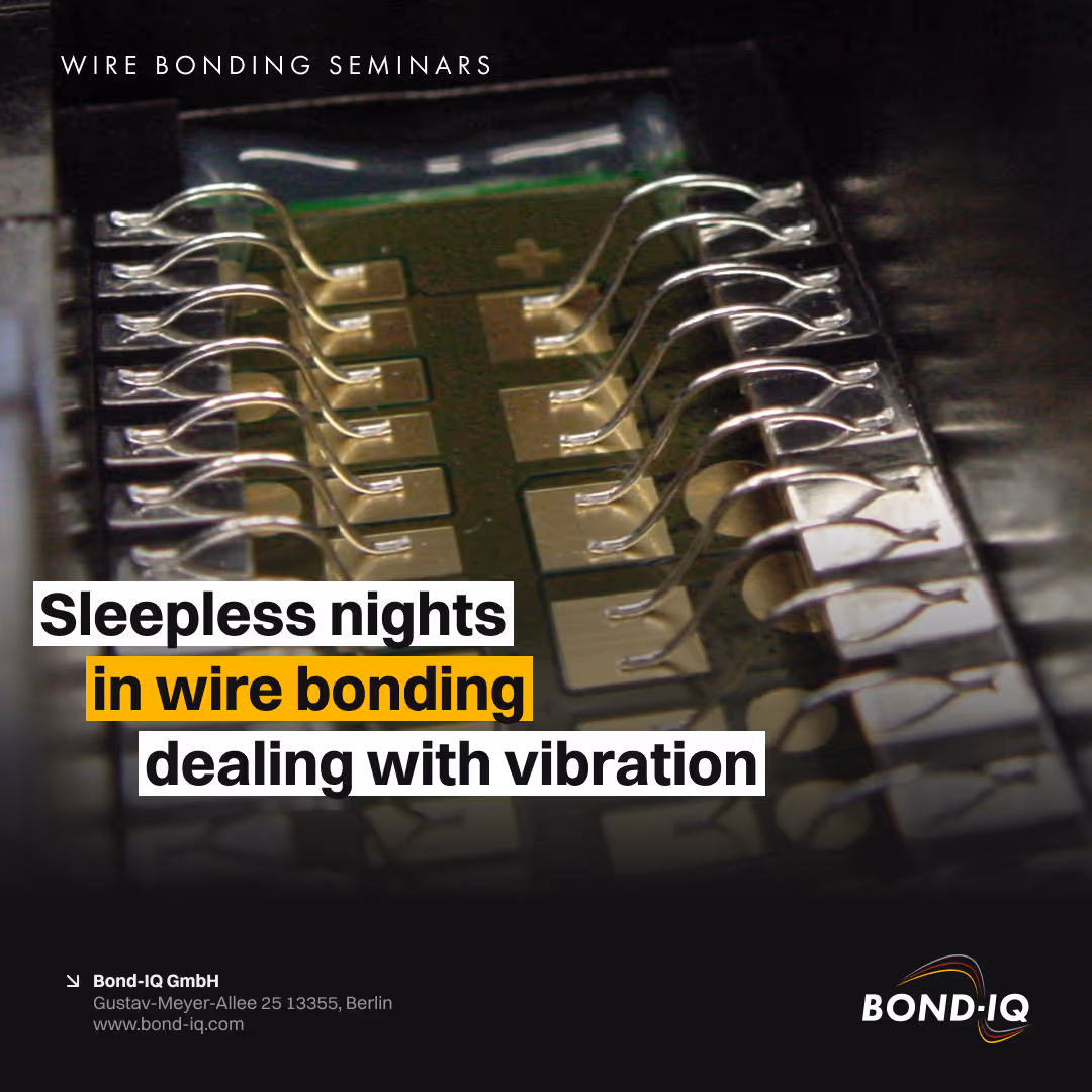
Sleepless Nights in Wire Bonding dealing with vibrations
The wire bonding process is deeply influenced by vibrational dynamics, which, if not properly understood and controlled, can lead to...
Sleepless Nights in Wire Bonding dealing with vibrations
Vibration Challenges in Wire Bonding 😱🥶
🤮 https://www.linkedin.com/pulse/ultrasonic-frequency-wire-bonding-stefan-schmitz
The wire bonding process is deeply influenced by vibrational dynamics, which, if not properly understood and controlled, can lead to reliability issues and process instability.
Here’s a breakdown of what we know and what the industry needs to move forward:
✅ What We Know
Two main influences affect the wire bonding process:
🔹 Vibration
🔹 Resonance (natural frequency)
Natural frequencies of bond pads cannot be controlled by process parameters – they must be avoided entirely by adequate design.
Dynamic frequency control taking place during the wire bonding process adds complexity, making vibrations harder to measure, to understand and predict in real time.
Laser vibrometers (my way started with systems made by Polytec ➡️ https://www.polytec.com/int/vibrometry/products) are currently the most suitable systems for in-process vibration measurement. Unfortunately its a measurement method that needs expertise and a well planned measurement setup and strategy.
Plastic injection-molded metal bond pads are particularly prone to these vibration-related issues. These components are usually bonded with thick wire. Problems with resonating bond pads cause sleepless nights and I have seen customers who have had to accept production downtimes of up to a week.
🔍 What Is Needed
Predictive measurement systems that can detect critical vibration behavior before it causes issues – ideally integrated into production lines.
A proven workflow between FEM modal analysis and wire bonding behavior during the design phase to anticipate and mitigate vibration problems early.
Smarter use of process data from bonding systems (e.g. frequency curves, current signals, additional sensors) to flag changing vibration behaviors across different material batches.
💡 As complexity increases, so must our tools and understanding.💡

1st EBL Young Researcher Award at the EBL 2018
Felix Fischer (Microsystems Engineering student at HTW Berlin) successfully presented his master's thesis in a paper and a presentation at the EBL Conference 2018, winning the prize for the best presentation. The thesis was carried out at Fraunhofer IZM Berlin and supported by Bond-IQ with extensive experiments and know-how, with the aim of investigating the semi-autocatalytic Au plating system on electrolessly deposited NiP for wire bonding applications with AlSi1 wire, e.g. for chip-on-board (COB) technology. The ability of the plating system to significantly reduce nickel corrosion during the deposition process and thus counteract coating adhesion problems during bonding is of great interest to users requiring stable bonding processes. The work has shown, in some cases with complex analysis, that there are still pitfalls in the technology and that further development is needed to solve the problem. Felix Fischer is continuing his research on this topic at Fraunhofer IZM and Bond-IQ will support his work.
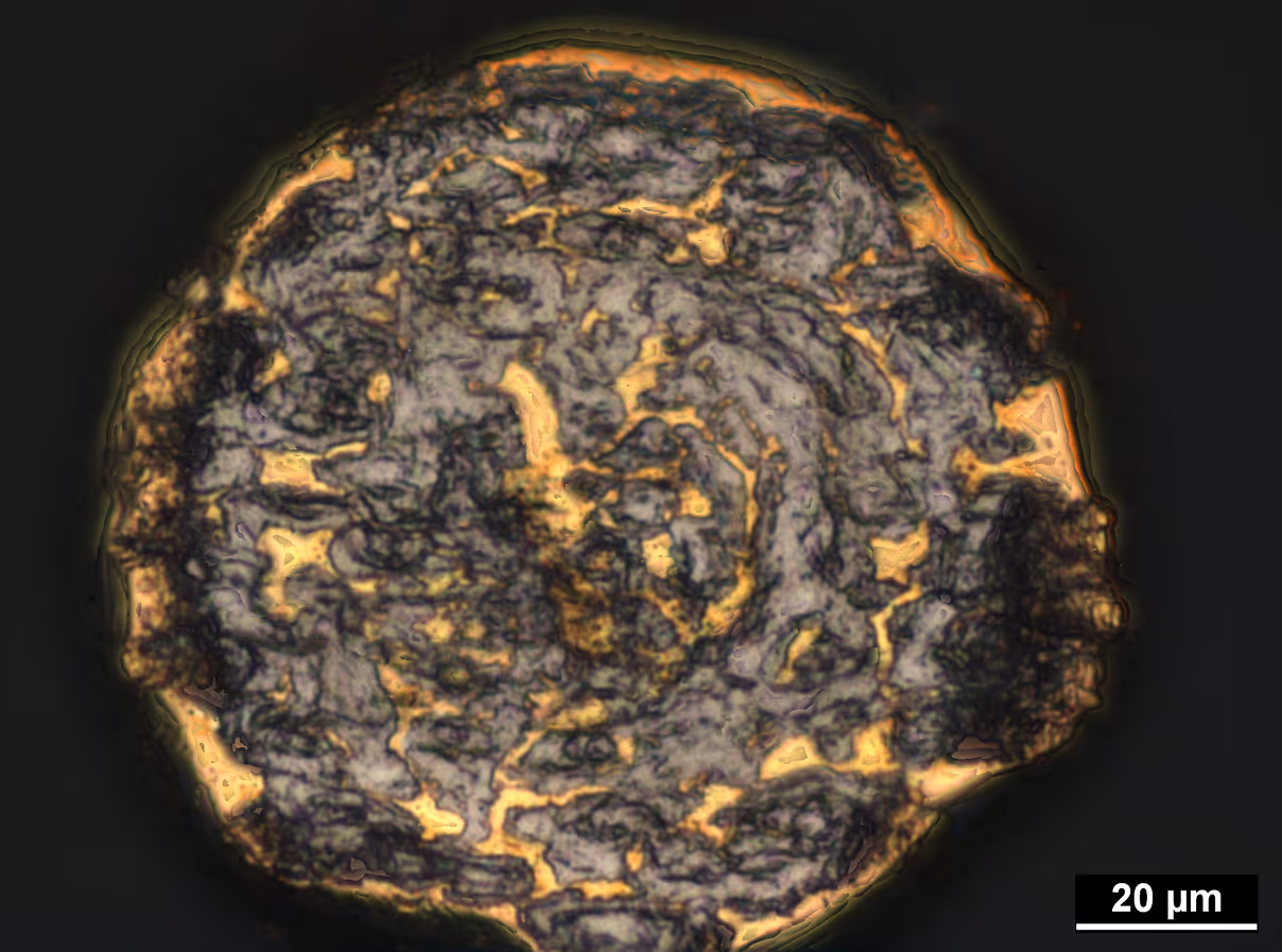
What it is?
This is the underside of a gold ball bond. On this surface, the intermetallics (IMC) formed between aluminum and gold during the bonding process are visible – and they are fairly evenly distributed.
🤔 But how does one obtain such an image? The underside of a ball bond is not visible. To make it accessible for inspection, the aluminum layer on which the ball was originally placed must first be removed. This is typically done by etching with sodium hydroxide (NaOH) for a duration of about 5 to 10 minutes – without the need for ultrasonic agitation or elevated temperatures during the etching process. 🤩
Once the aluminum is completely dissolved, the sample is carefully rinsed, thoroughly dried, and then the ball is flipped so that its underside can be examined under a microscope 🔬. In this state, one can either visually estimate the extent of intermetallic phase coverage or quantify it using image analysis techniques.
The percentage of the actually bonded area relative to the total available contact area beneath the ball is a key quality indicator. The greater the bonded area, the better the bond contact. The lifetime of the contact generally increases with a more extensive and uniform distribution of the intermetallics.
Therefore, although this preparation step to expose the bond interface is complex and time-consuming, it is highly valuable, as it allows for a reliable assessment of bond quality. However, the process is demanding, and both the preparation and image acquisition carry a significant risk of error. As such, it can realistically only be performed and interpret by well-trained and experienced process technologists.
For automotive qualification and high-reliability applications ⚠️, this method has now become nearly essential – at least during the process development phase 🧑🏻🔬👨🏽🔬.
✅ Think about how closely you look to check your wire bond contacts. First impressions can be deceiving...
With ball bonding, the volume of the ball (FAB) is determined by the flame-off process. This spherical volume is then transformed into the typical shape of a ball bond. This ball bond has a height (MBH - Mashed Ball Height) and a diameter (MBD - Mashed Ball Diameter). Just measuring the diameter is therefore not sufficient to check whether the FAB has been flamed in a defined manner and whether the bonding process has run smoothly.
Even when the ball looks good in a microscope, fluctuations in FAB volume can have the following effects:
🔸 Mashed Ball Height too flat or too high
🔸 Changed energy coupling/stress in the bond pad
🔸 Fluctuating connection quality
🔸 Highly scattering shear test results
Regularly checking the height of a ball bond is therefore part of state-of-the-art wire bond process control. This requires the right testing equipment and well-trained personnel 🙋🏼♂️🙋🏼♀️👨🏼💻👩🏻💻👨🏼🔧🧑🏻🔧.
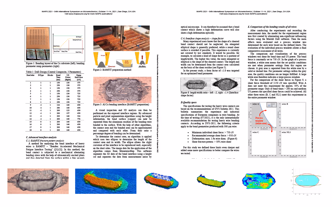
Advanced bonding interface inspection technique for process optimization in heavy wire bonding
Presented at the IMAPS conference in October 2021, this paper presents a novel methodology for analyzing the interface formation of heavy wire-bonded contacts. By combining the BAMFIT (Bondtec Accelerated Mechanical Fatigue Interface Testing) method, 3D fracture pattern measurements, and customized evaluation algorithms, this approach provides accurate data on the bonded interface area. Unlike traditional shear testing, this method directly measures the bonded area, allowing for improved parameter tuning for different material systems. The study examined four wire types with similar mechanical properties, using design of experiment (DoE) techniques to identify process windows and material-specific insights. The results highlight the benefits of accurately measuring the bonded area and illustrate where conventional shear testing has limitations in detailed analysis. This work provides valuable guidance for optimizing bonding processes and material selection.
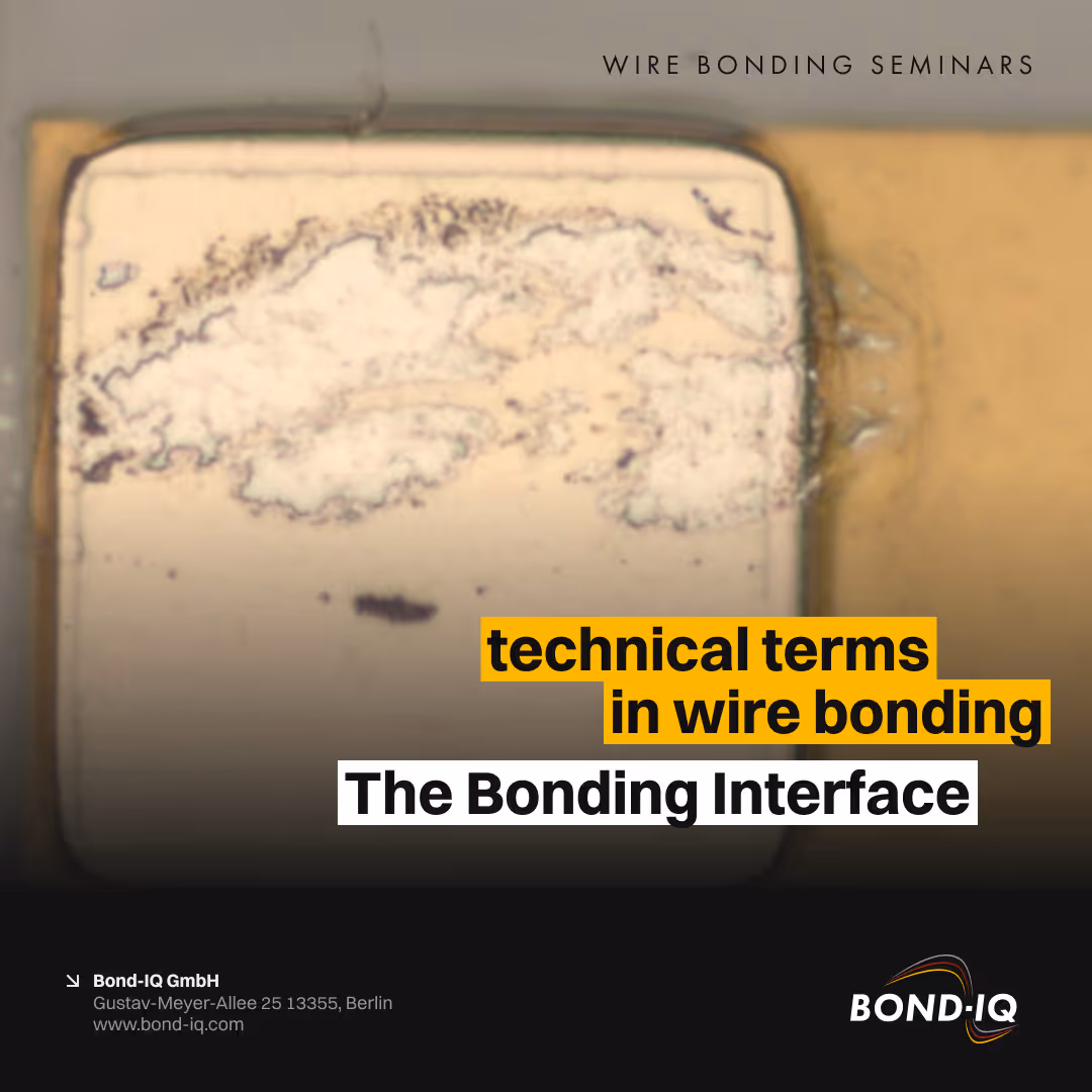
Technical terms in wire bonding - The Bonding Interface.
The bond interface consists of connected and unconnected regions. In practice, it is highly unlikely that 100% of the contacting surface will...
Technical terms in wire bonding - The Bonding Interface.
🔍 Technical term in wire bonding
The bonding interface
The bonding interface plays a central role in wire bonding – it is the region where the two bonding partners come into contact with each other. It is by no means a homogeneous region.
The bond interface consists of connected and unconnected regions. In practice, it is highly unlikely that 100% of the contacting surface will be completely bonded. Instead, a characteristic zone is formed during wire bonding process and its size and shape is determined by mechanical deformation of the bonding wire. In addition to various influencing factors such as cleanliness and roughness, three key parameters influence this wire bonding process:
🔧 Bond strength
⏱️ Bonding time
🔊 Ultrasonic power
Another important criterion for the properties of a bond interface is the material system:
1️⃣ Monometallic bond interface
Both bonding partners are made of the same metal, e.g., aluminum wire on an aluminum pad. Advantage: The interface is very stable – it changes only slightly during lifetime.
2️⃣ Bimetallic bond interface
The materials are different – for example, gold wire on aluminum. Here, significant changes in the interface can occur during the product life cycle, e.g., due to diffusion processes or corrosion. These can significantly affect the reliability of the connection.
🍟 Takeaway:
The bond interface is not just a physical contact surface – it is a complex area whose properties depend crucially on process parameters and material combinations. Especially with bimetallic interfaces, it is important to evaluate at an early stage how the interface will behave over the lifetime of the component – especially under the influence of temperature, humidity or electrical stress.
What methods do you use for evaluating the condition of a bond interface?
Revision of the wire bonding test standard DVS-2811
In February 2017, after more than 20 years, a revised version of the DVS-2811 test standard for wire bonding was published. From its start in September 2014 to its completion in December 2015, Bond-IQ worked intensively on the revision in a multi-client project, structuring and conducting the necessary experiments and coordinating the project. This work was done in close cooperation with Fraunhofer IZM Berlin. 25 project partners were involved and were fully convinced of the necessity and success of the project to revise the existing test standard. Just one year later, this was published as an official bulletin of the DVS Association under the previous number DVS-2811 with the addition of the version 02/2017. Since then, a comprehensive document for the testing of thin-wire and (still internationally unique) thick-wire bonded joints has been available. DVS Technical Bulletin 2811 is officially available from Beuth-Verlag in German and English.
Power Cycling and Wire Bond Reliability: The Critical Role of Wire Material and Diameter in Extending Lifetime
This research project examines the reliability of various types of aluminum heavy wire bonds utilized in power electronics, with a particular focus on their performance in MOSFET modules. Wire bonding is a common method used to connect electronic components, but the reliability of these bonds is of critical importance for long-term performance. The study examines the impact of varying aluminum wire materials and diameters on the durability of these wire bonds during power cycling, a process whereby the system is repeatedly turned on and off, resulting in temperature fluctuations.
Sintering and Copper Wire Bonding: Reducing Failure Rates in High-Thermal Power Modules
This paper presents a summary of the advancements in power electronic packaging, with a particular emphasis on the enhancement of reliability and performance under high temperatures. Power electronics are utilized in a multitude of devices to regulate electrical energy, and these systems encounter challenges due to the thermal stresses that are generated during operation. One area of focus is wire bonding, which involves the use of a metal wire to establish a connection between a semiconductor chip and other components.
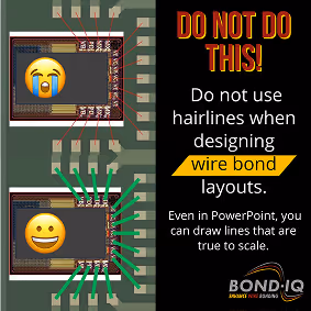
I often see hairlines in the layout program. Here you can zoom in beautifully - the line always stays thin. Everything fits perfectly. The surprise comes at the wire bonder when the first wires are pulled. Suddenly you realize that the distance between two wires is much too small. All of a sudden, you realize just how tight the tolerances are when there is just a slight shift or twist in the chip.
This can be avoided. 🤩
Even a simple presentation program like Powerpoint can do a good job here if no specialized layout programs are available at that moment:
Paste a screenshot of the layout in Powerpoint
Find a known dimension in the layout (e.g. chip size)
Insert a rectangle in Powerpoint and scale it to that dimension
Read the dimension of the rectangle in Powerpoint
Scale all lines and shapes relative to this rectangle
✅ Draw correctly scaled lines/rectangles as wires.
For number junkies: The effort here is between 45-60s per wire. So for a layout with 30 to 60 wires, you'll be busy for a maximum of 30 to 60 minutes. A time investment that pays off and can save a lot of money.
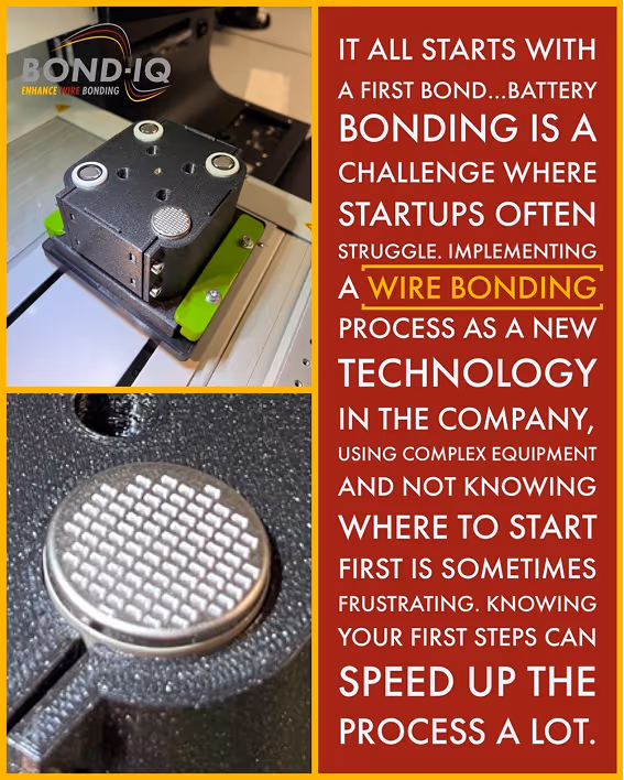
✅ Delving into the world of wire bonding of battery cells? Fantastic! Here's how to kickstart your journey in this technology.🚀
Master the Basics: Start with the fundamental principles, understanding the precise control of the three key parameters in ultrasonic bonding - ultrasonic vibrational power, normal force, and bonding time. They work together to create a strong bond between the wire and the bonding surface. Learn to use time controlled ramping of these parameters to get best bond strength and shear test results.
Learn about the correct quality testing methods. Pull-/Shear test is your friend but a good microscope is your forever-best-buddy. And start making friendship with laser cleaning.
Quality Assurance: Learn about the process integrated quality monitoring and control systems in wire bonders. This cutting-edge technology provides real-time feedback on bond quality, a valuable tool for improving yields and quality.
Practice Makes Perfect: Like any other skill, proficiency in wire bonding requires practice. Start with simple projects, gradually taking on more complex tasks as you build confidence and refine your technique. Find ways to use the available material as best as possible. Use individual cells and bond only the first bond - nearly every machine offers this feature (ask if you don´t know…be sure it is there).
Stay Updated: Technology evolves rapidly. Keep an eye on the latest developments in wire bonding, participate in forums, webinars, and workshops. Connect with industry peers on platforms like LinkedIn to share ideas and learn from their experiences.

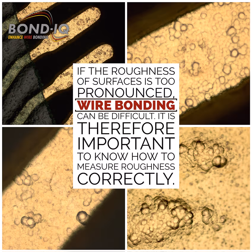
✅ In 2018, we successfully completed the „mikroRau“ project on the roughness of bond surfaces, which we coordinated for 26 industry partners. At that time, in addition to many exciting insights 💡, I had to learn an important detail about roughness measurement: For a defined, repeatable measurement that is traceable to roughness standards, specialized measurement technology is needed. Just "3D measuring" is not enough 🚫. This may sound plausible and not exactly like a grandiose novelty – but in my experience, many users underestimate exactly this point and measure with what they have 😱.
If the right equipment is available, it can be used in a variety of ways for quality inspection during wire bonding. I have summarized some examples here 👉🏻 https://bond-iq.de/wp-content/uploads/3D-measurement-wirebonding_EN.pdf
When measuring roughness, we were able to work out the following details:
✅ Be sure to work with surface roughness values!
✅ Use advanced optical inspection methods. These are ideal, especially for tests on bond pads.
✅ Pay attention to the limitations of the optics used and use methods that allow high critical angles for artifact-free measurement. The edge steepness of some bond surfaces overwhelms systems with low-cost solutions. Some methods are not suitable due to their principle.
✅ What cannot be measured reasonably cannot be corrected even with the best software 💻🚫.
✅ Ra values or Sa values are often used for evaluation, but they are rather unsuitable for bond surfaces ❌.
✅ Rz values or Sz values (or even better S10z values) are suitable for evaluation. However, this value expresses only one property of bond surfaces. It must be accompanied by other values. This is similar to the test methods for wire bonds (visual, mechanical and data-based) – here, too, one test alone is often not sufficient.
✅ Good software for analysis is expensive, very expensive 💰💸. But it has to be. Modern evaluation methods/algorithms can only be realized with it. Good software pays back this money in the end, because the use of templates speeds up the workflows considerably 🚀💯.
Reducing Wire Bond Failure: How Adjusting Bond Foot Angles Improves Power Module Reliability
The study focuses on wire bonding, a critical process for connecting electronic components within power modules. Wire bonding creates connections between a semiconductor chip and its supporting structure (substrate). In this research, scientists are examining how different angles at which the wire touches the chip, known as the bond foot angle, affect the longevity of these bonds. A larger bond foot angle tends to reduce the life of the wire bond because it introduces additional stress during operation. The team used both experiments and simulations to test the effects of varying bond foot angles on wire bond reliability.
Advancements in Copper Ball-Wedge Wire Bonding: A Cost-Effective Alternative to Gold in Semiconductor Manufacturing
The literature review examines advancements in copper (Cu) ball-wedge bonding, a technique utilized to establish connections between wires in electronic devices. Historically, gold (Au) was the material of choice due to its resistance to corrosion. However, the increasing costs associated with gold have prompted the exploration of alternative materials, such as copper. Copper offers superior electrical performance, but it also presents challenges such as oxidation (rusting) and increased hardness, which complicate the bonding process.
Investigating the Inaccuracies in Wire Bonding Pull Testing and Introducing a New Analytical Model for Improved Quality Control
This study examines the process of wire bonding pull testing, which represents a pivotal quality control step in microelectronics, particularly in fields such as automotive and sensor manufacturing. The process of wire bonding entails the formation of connections between small wires and electronic components. It is of paramount importance to ensure that these bonds are robust in order to guarantee the reliability of the final product.
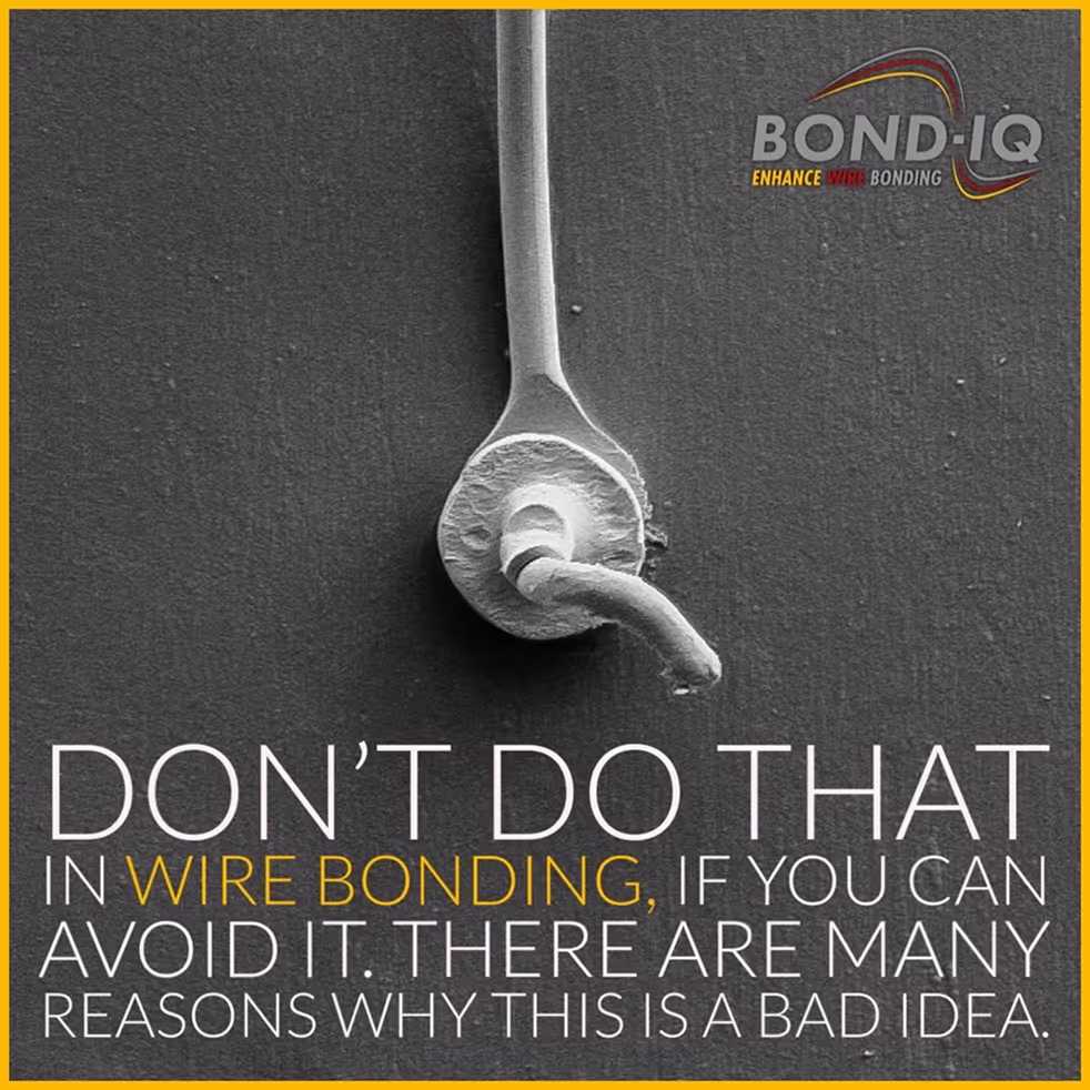
✅ If a wire bond contact cannot be reliably contacted on a surface, then there is a reason for this. Trying to secure this contact mechanically is actually not such a good idea. Or what do you think?
In older processes, I still see the so-called safety bumps (or security bumps) relatively often. The subsequently bonded ball is supposed to fix the wedge/stitch mechanically even better and thus ensure that the required quality is achieved and the product is manufactured sufficiently robustly. This has been proven to work. A pull test on a wedge secured by means of a safety bump usually withstands higher pull forces. All good, actually. But I still don't think it's a good method in terms of a robust process. The following thoughts on this:
💣 First of all, the root cause of the poor bond quality is not fixed. The problem gets a band-aid 🩹🚑🤕 on it. A bug fix without fixing the bug. The most common cause...contamination of the surface with any dirt from the manufacturing or pre-processes. So better get rid of it and bond on clean surfaces.
💥 What do you do if the wedge doesn't bond on the surface? Correct - you crank the parameters up. As a result, a capillary imprint is often left on the surface and destroys the metallization. The safety bump is now placed on this destroyed area. This is not a good basis for a robust contact.
📍 Where do you actually place the ball optimally? There is a regular discussion about this. Sure, you can optimize that by means of pull tests. But what if the position of the safety bump varies? Its safety function depends very much on where exactly it is placed. The problem: If it is placed incorrectly (or is even missing and this is overlooked), the contact is electrically ok and is delivered to the customer. Mechanically, this contact is then far from robust.
So what would be the better strategy?
Look at your process and solve the root causes of the problems. Acquire the necessary know-how so that you don't have to deal with such problems by fixing bugs. Train your staff well so they can find bugs and determine root causes. No matter how you do the math - good training always pays off!
⭐️ "An investment in knowledge always pays the best interest." (Benjamin Franklin)
⭐️Or just turn it around and make it a stitch-on-bump (SOB, SSB, BSOB) process. Yes, this process also requires a longer process time. But it is a much more defined process. Feel free to discuss it in the comments.